A crystal oscillator, also known as a crystal oscillator, is an electronic oscillator that uses a crystal as a frequency selection element to obtain the inverse piezoelectric effect. It utilizes the mechanical resonance of a vibrating crystal with piezoelectric properties to obtain electrical signals with high precision frequencies. Crystal oscillators are considered superior to ceramic resonators because of their higher stability, higher quality, lower cost and smaller size. The following is a brief introduction to the technical terms related to crystal oscillators for your reference.
1. Resonance frequency
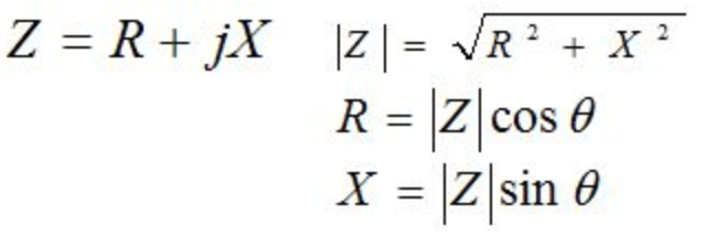
In the resonance characteristics of a crystal resonator, the resonance frequency is the lower frequency point at which the impedance becomes resistance at two points.
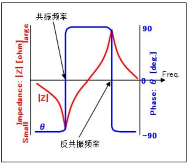
Fig. Crystal Resonator Resonance Characteristics
The frequency between two points when impedance Z becomes a resistive element. At these two points, the phase is 0. The point where the frequency is lower is called the resonance frequency. Another point is called the anti-resonance frequency.
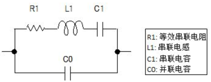
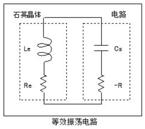
2. Equivalent circuit
The figure below shows the resonance characteristics of a crystal resonator composed of resistance, inductance, and capacitance. R1 is called the equivalent series resistance in the equivalent circuit and is an important characteristic of the crystal resonator.
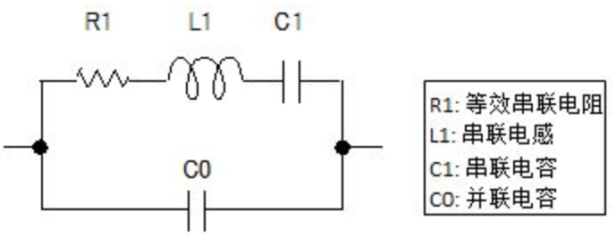
3. Equivalent series resistance (R1)
The resistance in the series branch of the crystal resonator equivalent circuit.
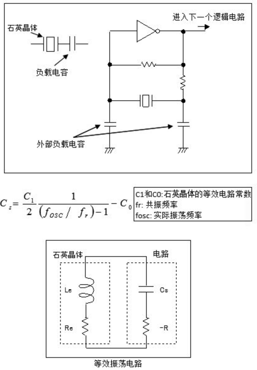
4. Load capacitance (Cs)
Let the crystal resonator have a capacitance that loads the resonant frequency. In the actual oscillation circuit, the actual capacitance connecting the crystal resonator is generated by the external load capacitance, IC stray, PCB, etc. It can also be calculated using the following formula:
5. Load resonance frequency (fL)
The load resonant frequency is the resonant frequency of the load capacitor in series in the crystal resonator, which is higher than the resonant frequency. Due to the capacitance difference between the actual value and the rated value in the crystal resonator specification, there is a frequency difference between the actual and rated oscillation frequency.
It can also be calculated using the following formula:
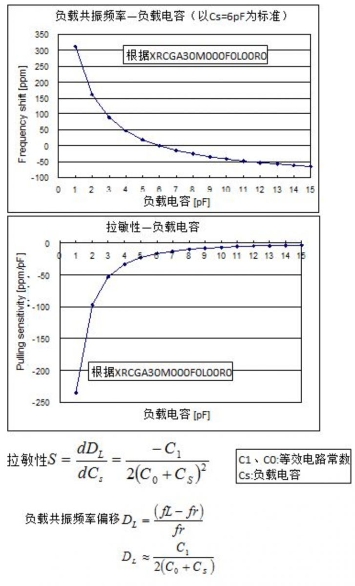
6. Laminarity
The graph above shows the shift in load resonant frequency (fL) due to changes in load capacitance. The slope of each point in this graph is the pull-sensitivity. See the figure below. With a load capacitance of 6pF, the pull-sensitivity is -17ppm/pF. (When the load capacitance changes by 1pF, the frequency shift is 17ppm). It can also be calculated using the following formula:
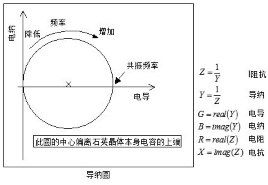
7. Admittance circle
The figure below is the resonance characteristic of a crystal resonator plotted on the admittance plane coordinates (conductance-susceptance). Since it is drawn as a circle, it is called the admittance circle. At frequencies below the resonant frequency, the admittance is close to the origin. As the frequency increases, the admittance draws a circle in a clockwise direction.
8. Oscillation margin
That is, the margin for oscillation stop, which is also the most important term in oscillation circuits. The oscillation margin depends on the components that make up the oscillation circuit (crystal resonator, MCU, capacitors, and resistors). Murata recommends maintaining an oscillation margin of 5 times or more. For more details, please pay attention to the second lecture of this series of lectures.
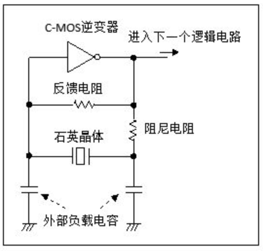
9. Negative resistance (-R)
Negative resistance is the signal amplification ability of the oscillator circuit represented by impedance. It is a negative value because it acts in the opposite direction of resistance. The higher the negative resistance and the smaller the lower the amplification ability of the oscillator circuit. The negative resistance in the oscillation circuit depends on the characteristics of the CMOS inverter, feedback resistance, damping resistance and external load capacitance.
10. Driving power
The driving power refers to the power consumption of the crystal resonator in the oscillation circuit. It depends not only on the equivalent series resistance of the crystal resonator, but also on the components (MCU, capacitors and resistors) that make up the oscillation circuit. When the drive power is exceeded, the frequency-time performance will exhibit abnormal characteristics. When designing an oscillation circuit, it is best to check the drive power.
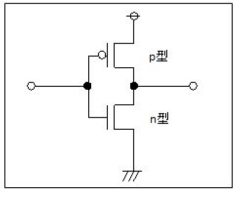
11.C-MOS inverter
C-MOSs are complementary MOSs that make up interconnected p- and n-type MOSFETs. In the figure below, it functions as an inverter (logic inverter circuit NOT).
12. Oscillation circuit
In amplifier circuits equipped with C-MOS inverters or transistors, the so-called "oscillation circuit" is what connects the output to the input in order to continuously amplify the feedback. Only feedback through the crystal resonator can select and amplify the signal at the resonant frequency.