
introduction
With the rapid development of social economy, the land resources required for the development of various social industries, such as highways, railways, airports, industrial parks, real estate and other projects, are also rapidly increasing. With the improvement of people's living standards, the government and the The public awareness of environmental protection has gradually increased, and the emergence of many nature reserves, scenic spots, and ecological red lines has also made it more difficult to select transmission lines. Therefore, how to improve the transmission capacity of the transmission line unit corridor and meet the growing demand for electric energy with relatively less land resources is an urgent problem to be solved in the current power grid development.
At present, some domestic power grids adopt a compact transmission line scheme with upper and lower arrangement. The two-circuit conductors are arranged in an inverted triangle, and the loops are arranged vertically up and down. The distance between conductors is reduced. Calculate the electromagnetic induction between the lines to ensure the safety of line equipment and personal safety. Therefore, this paper studies the electromagnetic induction between the circuits of the 500kV vertical double-circuit compact transmission line.
1 Computational Model
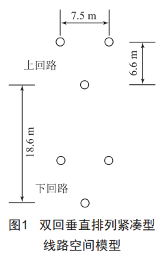
In this paper, a 500kV vertical double-circuit compact line is used as an example. The conductor adopts 4×JL/G2A-720/50 steel core aluminum stranded wire, the split spacing is 500mm, and the ground wire adopts JLB35-150 aluminum clad steel stranded wire. The average soil resistance The rate is 500Q m, the operating voltage is 525kV, the normal transmission capacity is 2260MVA (economic current density 0.9A/mm2), the ambient temperature is 35℃, the wind speed is 0.5m/s, and the solar radiation power density is 1000w/m2. The spatial model of the vertically arranged double-circuit compact transmission line is shown in Figure 1. The horizontal distance between the two-phase conductors is 7.5m, and the distance between the upper and lower conductors is 6.5m.
For the theoretical calculation of the asymmetry problem of ultra-high voltage transmission lines, there are two practical methods in engineering application: manual method and simulation method. The manual method belongs to the sequence component method, and the calculation process is relatively simple, but it is only suitable for single-circuit, not for the double-circuit studied in this paper. The simulation method applies electromagnetic transient calculation programs such as ATP/EMTP, PsCAD/EMTDC and other software to the transmission line For simulation calculation, many factors can be considered in the calculation process, such as the influence of phase sequence arrangement, double loop, multi loop, transposition, etc., the calculation results are more accurate and more reasonable. Therefore, this paper uses the open platform ATP/EMTP software to simulate and calculate the electromagnetic induction characteristics of the new compact circuit.
This paper focuses on the electromagnetic induction of transmission lines, so the influence of the entire transmission network is not considered in the calculation, and the model is modeled according to one end of the power supply and one end of the load, as shown in Figure 2.
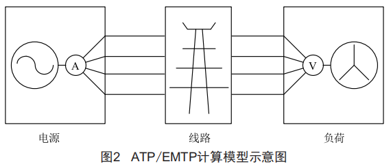
The equivalent load impedance value is calculated according to the system voltage, transmission power and power factor. In order to reflect the unbalance of the line, a symmetrical three-phase load is used. Since the voltage and current unbalance of the analysis line belongs to the category of steady-state analysis, the distributed "PI" model is adopted for the line model.
3 Classification of induced voltage
In the double-circuit line on the same tower, when an accident occurs in one circuit or the operation needs to be outaged for maintenance, due to the coupling effect between the circuits, the normally running circuit will generate an induced voltage on the outage circuit. In order to meet the safety needs, the maintenance circuit usually needs to be grounded. According to the opening and closing of the grounding switch at both ends of the line, it can be mainly divided into the following four working conditions:
(1) The knife switches at both ends of the maintenance circuit are not grounded. At this time, the operation circuit generates an electrostatic induction voltage on the maintenance circuit:
(2) One end of the maintenance loop is grounded, and the running loop generates an electrostatic induction current on the grounding point of the maintenance loop:
(3) One end of the maintenance loop is grounded, and the operation loop generates electromagnetic induction voltage at the non-grounded point of the maintenance loop:
(4) The knife gates at both ends of the maintenance loop are grounded, and the operation loop generates electromagnetic induction current at the grounding point of the maintenance loop.
4 Calculation of induced voltage and induced current of non-transposed line
This section calculates the induced voltage and current without transposition when the line length is 100km and 200km, and calculates the following two cases:
(1) The operating circuit voltage is 1.1U, and the operating current is economical current:
(2) The operating loop voltage is 1.05U, and the operating current is the current under the condition of N-1. After calculation, when the length of the 500kV vertical double-circuit compact line is 100km without transposition, the maximum electrostatic induction is 36.8kV, and the maximum electromagnetic induction current is 138.7A; when the line length is 200km without transposition, the maximum electrostatic induction is 37.1kV. , The maximum value of electromagnetic induction current is 146A. Corresponding protective measures should be taken in the selection of the grounding switch at the substation end and in the construction and maintenance of the line.
5 Conclusion
This paper uses ATP/EMTP software to calculate and analyze the induced voltage and induced current between the circuits of the vertically arranged double-circuit compact line. The calculation results show that when the length of the 500kV vertical double-circuit compact line is 100km without transposition, the maximum electrostatic induction is 36.8kV, and the maximum electromagnetic induction current is 138.7A; when the line length is 200km without transposition, the maximum electrostatic induction is 37.1 kV, the maximum value of electromagnetic induction current is 146A. Corresponding protective measures should be taken in the selection of the grounding switch at the substation end and in the construction and maintenance of the line.